Dry Flocculant Mixing and Feeding Design Considerations

This is a guest post by Bill Hancock, President of Zeroday Enterprises

Dry Flocculant Mixing and Feeding Design Considerations

Dry flocculant wetting, dissolving, mixing and solution feeding must be done under very specific controlled conditions that account for the flocculant’s unique physical and chemical characteristics. Failure to ensure proper polymer solution preparation and feeding can result in mix-feed system plugging and erratic operation, process control issues and wasted polymer.

Key flocculant characteristics that must be considered for proper flocculant mixing and use are summarized below:

1)    Flocculant powders are hydroscopic. Storage and dry polymer feeding systems must ensure minimum air contact as the particles will adsorb moisture which initiates flocculant dissolution. Dissolving particles are very sticky and consequently will aggregate into larger pieces and chunks. These larger pieces and chunks dissolve slower and often can plug equipment causing mix system and even process operational disruptions.

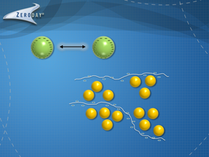
2)    Water wetted flocculant particles can aggregate into masses. Since flocculant particles dissolve proportionately to exposed surface area, particle aggregates that have stuck together result in significantly reduced dissolution rate during mixing. If the flocculant aggregates do not fully dissolve within the set system residence time, these partially flocculant masses will pass through the mix system and process unused. And possibly plug equipment. Note: flocculant particles/aggregates will hydrolyze throughout into a clear gel which refract light differently than water, these masses are called ‘fish eyes’ because can predominantly see the light refraction, not the mass itself.

3)    It is very important to initially wet each flocculant particle. The mixing system must be designed in the first step of the mixing process to wet each particle individually and immediately, and subsequently ensure these wetted particles do not aggregate or agglomerate. There are two main mix system flocculant particle wetting categories.

  1. Augering flocculant particles into a funnel with plenty of water flowing in the funnel followed by some motive dispersive force to ensure any particles that might stick together will be pulled apart.
  2. The flocculant particles are air blown from an auger into a large diameter hose to the top of the mix tank where cascading water inside a tube wets the particles which enters the mix tank and impeller.

4)    Flocculant dissolution time variable. Flocculants dissolve at different rates, primarily dependent on the following factors.

  1. Type of polymer charge
  2. Flocculant charge level
  3. Water temperature and chemistry

Required mix times can range from 30-90 minutes are designed into a mix system.

5)    Flocculant solutions are viscous. Dissolved long chain flocculants introduce solution drag that is expressed as viscosity. The amount of viscosity is dependent on the flocculant charge, charge level, temperature, concentration and molecule chain length. More viscous solutions require more mixing power. To ensure the flocculant molecule chains are not broken, balancing the amount of power in mixing and the type of mixing are crucial for minimizing dissolved flocculant chain damage.

6)    Low shear pumps must be used for flocculant solution transfer and feeding. The two more predominate low shear pump types are progressing and diaphragm. More specifically, examples of pumps that are acceptable include progressive cavity, peristaltic, gear, lobe and air operated diaphragm.

7)    Flocculant solutions typically provide best performance at ≤ 0.1% concentrations. To optimize flocculant mixing system sizing, flocculant solutions are often designed to be mixed to 0.25-0.50% maximum concentration. Once dissolved, the flocculants will dilute readily with teed in water down stream of the flocculant feed pump to obtain the final target 0.1% concentration.

Flocculant mixing and feeding is not highly complex. But the unique flocculant characteristics accounted and designed into a mixing-feeding system to ensure optimum preparation and minimized consumption.

Bill Hancock is an internationally recognized expert in mineral processing technologies, technical marketing management and water treatment. Hancock founded and owns Zeroday Enterprises which supplies chemical mix-feed systems, LTM conductive slurry level monitoring probes, peristaltic hose and tube pumps, mixers and flocculant and coagulant chemicals. He also founded Argo Consulting—a technical and technical marketing consulting practice focused on providing mineral processing, water treatment and technical marketing consulting services to the mining industry.

Accurate Slurry and Pulp Level Measurement

This is a guest post by Bill Hancock, President of Zeroday Enterprises

Accurate Slurry and Pulp Level Measurement

Accurate Slurry and Pulp Level Measurement when there is a froth or foam on top of the flotation cell, mixing tank or sump can be challenging under many conditions. Reasons for pulp level monitoring and measurement include:

  1. Mechanical measuring devices such as float balls and ultrasonic targets can become covered with solids causing the device to hang up, become heavy and sit in the slurry deeper and/or the slide mechanism gets jammed and stuck preventing smooth operation.
  2. Slurry density (% solids) fluctuations cause float-ultrasonic and pressure differential devises to vary. Changing slurry apparent specific gravity will cause the float ball to ride higher or lower in the slurry even if the slurry level stays constant. Pressure differential devices, such as bubble tubes and pressure differential electronic sensors, measure based on slurry weight above the device so will provide proportional pulp level readings as slurry densities change.
  3. Basic froth mechanics, particularly in flotation cells, where bottom layers of the froth bed will be quite wet because fine bubbles coursing upward to the froth will push entrained slurry into the froth. As the fine bubbles coalesce into larger bubbles and rise to the top of the froth bed, this slurry drains back into the cell. When froth characteristics or operating conditions change, the amount of water and slurry in the bottom layers of the froth will vary and make proper froth-slurry interface depth measurement more problematic.

Point #3 is worth dwelling on because this is often overlooked or not well understood. A rough representation of a mineral flotation froth cross section is provided below. The fine bubbles generated by the flotation cell impeller rise to the bottom of the froth bed and coalesce into larger bubbles as these rise in the froth. The values are upgraded as the bubbles coalesce because the bubble surface area decreases with the result being less particle carrying capacity. Probabilistically the weakest, least hydrophobic particles are released and drain back into the cell.

slurry and pulp
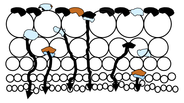
There is a massive amount of air in a flotation cell, typically 12-25% of a float cell’s total volume, which rises enmass to the froth layer as fine bubbles. Much slurry is pushed into the lower froth bed which is held in the voids between the bubbles until the slurry can drain back into the cell. As illustrated in the figure, there is more slurry in the lower froth bed than higher due to drainage.

This slurry in the void spaces between the bubbles must and will drain to the float cell. However there will be some slurry holdup before draining which can make the pulp-froth interface indistinct and difficult to define depending on the amount of slurry held in the froth. The amount of slurry carried into the froth can significantly vary.

Mechanical and pressure differential slurry level measuring techniques can have difficulties consistently and precisely monitoring the pulp-froth interface level under these conditions. However, electrical conductance pulp level measurement techniques can more effectively and consistently define the froth-pulp level interface height.

The conductive LTM pulp level monitoring probe technology dramatically reduces the complication of slurry level interface monitoring under a wide range of froth and flotation conditions. Because the probe is quite sensitive and measures at very low conductance levels, the probe capably and consistently measures at very low slurry (e.g. water) concentrations.

It is possible to define the slurry-froth interface level as the precise point where there is distinctly very low conductance due to a lack of slurry, at the depth where there is a predominance of air. In essence this is an electrical circuit on-off signal where the LTM pulp level monitoring probe identifies the depth where the froth is sufficiently drained preventing electrical current transmittance. From a logical reasoning standpoint this is a practical and effective measure. And is the slurry level interface level the LTM probe monitors.

Bill Hancock is an internationally recognized expert in mineral processing technologies, technical marketing management and water treatment. Hancock founded and owns Zeroday Enterprises which supplies chemical mix-feed systems, LTM conductive slurry level monitoring probes, peristaltic hose and tube pumps, mixers and flocculant and coagulant chemicals. He also founded Argo Consulting—a technical and technical marketing consulting practice focused on providing mineral processing, water treatment and technical marketing consulting services to the mining industry.

Thickeners: How they Operate

This is a guest post by Bill Hancock, President of Zeroday Enterprises

Thickeners: How they Operate

The most common solids-liquid (S/L) unit operation is thickening. A wide variety of thickeners are used including conventional, deep well, paste, high rate and clarifiers which is a thickener subclass used for removing solids from turbid or very low % solids waters. Thickeners are mechanically continuous process equipment which operates on a particle/floccule sedimentation principle where in simplest terms the solids settle to the bottom of the thickener tank and the water overflows the tank.

Essential elements common to thickeners include:

a)  Feedwell: where the slurry or water is introduced into the thickener which confines the kinetic energy of the incoming waters to minimize overall tank turbulence as well as directing the flow downward into the thickener

b)  Rake mechanism: or similar device that pulls the settled solids/mud to the center of the tank; as the rakes travel through the mud, this plays an additional important role in disturbing the mud and releasing additional water retained by the settled mud

c)  Under flow pump: which can be of several types including peristaltic, centrifugal, diaphragm and progressive cavity.

Thickeners are designed to operate continuously with slurry/water consistently flowing into the centerwell with thickener underflow pumping balanced to maintain a mud bed in the thickener. Key to thickener operational efficiency is the solids must be able to settle 2-4 times faster than the nominal water up flow rate. High feed solids recoveries reporting to the bottom of the thickener ensures high solids recovery and high overflow clarity levels.

Modern thickeners are designed based on use of highly effective synthetic (polyacrylamide) flocculants, ensuring high solids capture and adequate settling rates. Coagulants are sometimes also used when fine particle recovery is a challenge with flocculants alone. Fine particle recovery is needed to maximize thickener overflow clarity, minimize sands-slime separation in the bed which causes torque issues and to ensure bed solids flowability. Additionally coagulants can have positive downstream operational benefits such as in filters.

Flocculants are typically introduced either to the slurry-water pipe feeding the thickener, to a feed tank before the thickener, to the centerwell or a combination of these addition points. Where flocculant is optimally dosed is typically determined by plant evaluation and varies from operation to operation and is influenced by solids substrate, particle sizes and system specific factors. If coagulants are used, typically these are dosed upsteam of the flocculant addition point; however, in mineral concentrates, most often the best response is dosing coagulant after the flocculant.

Settled solids at the bottom of the thickener is called ‘mud’. The goal is to maximize the % solids in the underflow to recover as much water as possible for reuse. Primary means for controlling % solids is by mud depth and flocculant dosage. Deeper mud depths increase % solids because mud weight will cause more water to be released. Higher flocculant dosages, within a normal dosage rate range, will result in higher % solids. The % solids is typically limited by the thickener’s ability to transfer mud from the thickener and pumping the underflow because viscosity and slurry density increases dramatically with increasing % solids.

The simple animation below that shows only flocculant addition (not coagulant) illustrates these thickener operational principles.


Bill Hancock is an internationally recognized expert in mineral processing technologies, technical marketing management and water treatment. Hancock founded and owns Zeroday Enterprises which supplies chemical mix-feed systems, LTM conductive slurry level monitoring probes, peristaltic hose and tube pumps, mixers and flocculant and coagulant chemicals. He also founded Argo Consulting—a technical and technical marketing consulting practice focused on providing mineral processing, water treatment and technical marketing consulting services to the mining industry.

Flocculants: How Do They Work and Why?

This is a guest post by Bill Hancock, President of Zeroday Enterprises

How Do Flocculants Work and Why?

Have you ever wondered how flocculants work at the colloid (small particle) level?

Flocculants enhance, and are often required to make possible solid-liquid separations from turbid to high percent solids in water.  Typically, solid particle sizes in water have a wide normal distribution and are inorganic and organic based.   If these particles are denser than water, the particles will settle to the bottom of a container if given sufficient time; however, many of the smaller, lighter particles remain suspended (think a cloudy mud puddle that appears to swirl with activity) for a much longer time than allowed with a typical residence time.  That is because the particles, or colloids, are small enough to remain suspended by external forces including Brownian motion (interaction with the water molecules), thermal currents, dispersive surface charges and the like.  These are the hardest particles to treat because they are so fine and do not easily and quickly settle.

How do Flocculants work and why?

Unless the particles are uniformly coarse (depending on the water chemistry conditions and relative solid and water densities, coarse particles might be considered greater than 100 mesh or greater than 210 microns) and rapidly settle by gravity, flocculants are required to aggregate multiple particles together as ‘floccules’ which are pseudo-large particles.  Enter the flocculants!

Polymers are ubiquitous materials ranging from nylon, polyethylene plastics, Teflon, and starches to amino acids.  Flocculants belong to the water soluble polymer class, and so they fully dissolve in water.  These are acrylamide based with functionality groups which allow the polymers to readily chemically adsorb to particles.  These polymers are very long (for perspective, if you expanded a flocculant molecule to 1 inch in diameter, the total length would be on the order of 1.25 miles long!)  As flocculant molecules dissolve in water, these molecular chains (ropes) are free to uncoil and expand, but are never completely linear due to random Brownian motion and water thermal current effects.

In effect, these flocculant ropes lasso aggregates of particles together.  Since the polymer chains are very long, these polymers agglomerate multiple colloidal and coarse particles together.  As these flocculated aggregates continue to mix, the polymer rope continues pulling the particle aggregate into a tighter and denser floccule, which causes the particles to settle more readily. The larger floccules are more easily filtered, centrifuged and floated in a dissolved air flotation unit.

A simple visual demonstration of this process is represented in the accompanying animation video.  The animation shows the initial step of ‘coagulation’ where a short cationic (positive) charged polymer coagulant is added to partially neutralize the repulsive particle negative charges and induces pin flocc aggregation of the colloidal particles.  Then the flocculant molecules ‘lasso’ and flocculate these pin floccs into larger floccules.

Bill Hancock is an internationally recognized expert in mineral processing technologies, technical marketing management and water treatment. Hancock founded and owns Zeroday Enterprises which supplies chemical mix-feed systems, LTM conductive slurry level monitoring probes, peristaltic hose and tube pumps, mixers and flocculant and coagulant chemicals. He also founded Argo Consulting—a technical and technical marketing consulting practice focused on providing mineral processing, water treatment and technical marketing consulting services to the mining industry.